Quick Links:
Project Overview:
When I set out to create a Digital Dash for my 350z I faced many challenges and unanswered questions. I spent many
weekends testing and figuring out solutions that simply weren't documented anywhere online. This post is my way of
sharing what I've learned so that others attempting a similar project have the information I wish I'd had at the
start. If you're looking, to build your own Digital Dash, consider this a guide or at least some
inspiration.
So, what exactly is this Digital Dash? As the name suggests, it's a system that displays and logs a wide range of
real-time data from your car, sourced from various inputs including an OBDII scanner, accelerometer, gyroscope,
and
GPS. This data can be displayed and logged for virtually any use case you can imagine. A few examples include: AFR
(air fuel ratio), boost pressure, oil temp, coolant temp, throttle position, intake manifold pressure, fuel
pressure, RPM, speed, check engine lights, G-force meter, 0-60 timer, lap timer, maintenance interval tacking,
etc. The possibilities are endless, limited only by your creativity and the available data inputs. This project is
powered by a Raspberry pi 4 Model B (8GB) running AOSP (Android 13), equipped with an Adafruit Ultimate GPS HAT
and MPU-6050 6-axis module for enhanced data collection. All of this is powered by the car's 12v system and
displayed through a custom Android app I'm developing to visualize and log the data.
Okay now let's jump into it:
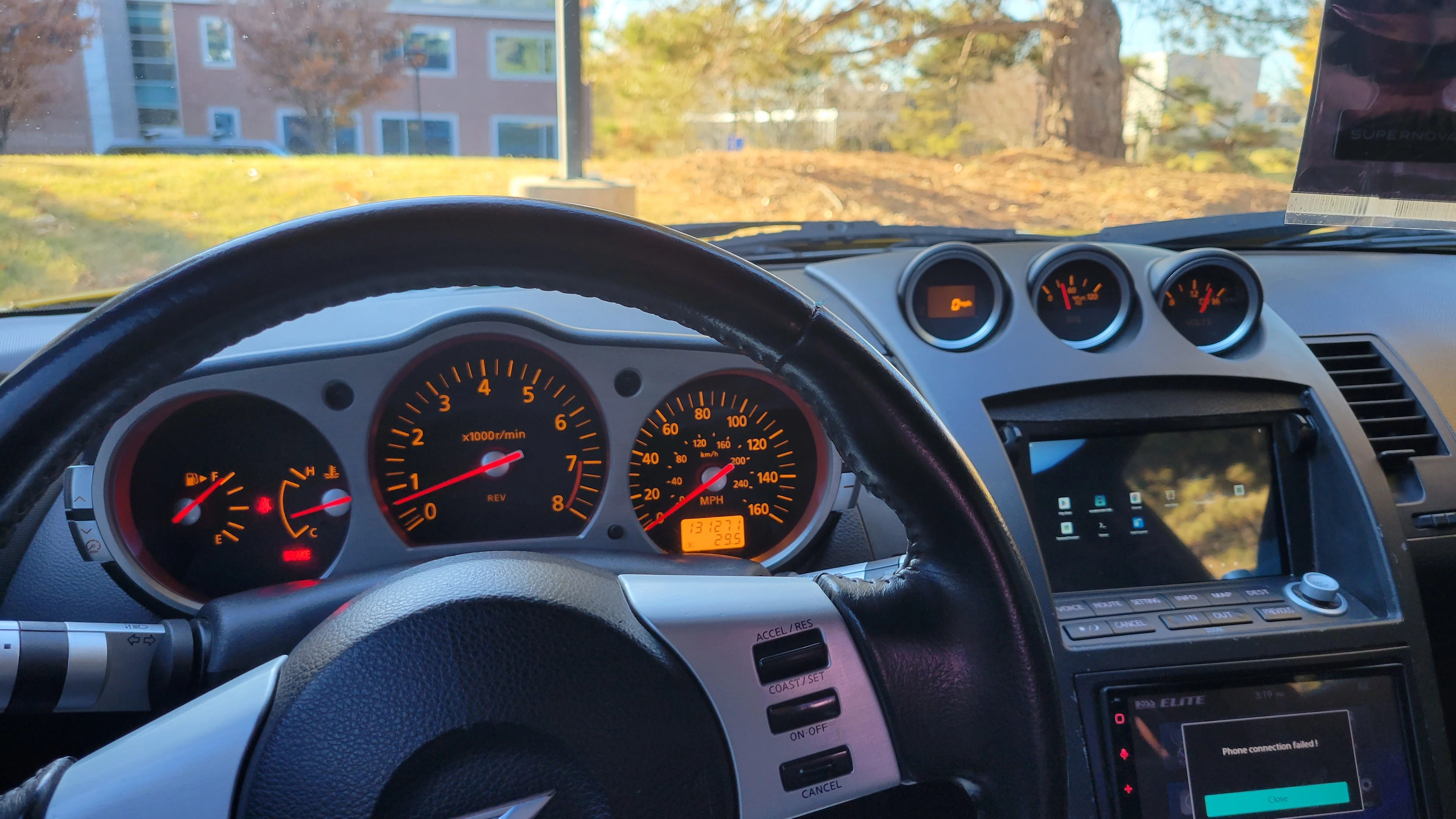
This project began when I was having constant overheating issues with my 350z and realized that the factory coolant temperature gauge wasn't cutting it. The stock gauge is very low resolution and by the time it indicates temperatures are rising it's too late and the car’s already overheating. I needed a better solution, one that could provide real-time, accurate numerical readings. Luckily, I had a Raspberry pi 4B (8GB) sitting around from an old project of mine where I had it running Pi-hole. After I did some research on what the best way to do this would be. I found there was a project out there called KonstaKANG.com where they were able to get LineageOS working on a Raspberry pi. So, I downloaded AOSP (Android 13) off their website and got that installed. I followed this fantastic YouTube tutorial to get it up and running on my pi. This laid the groundwork for the custom Digital Dash I was about to create.
Why I chose a Pi:
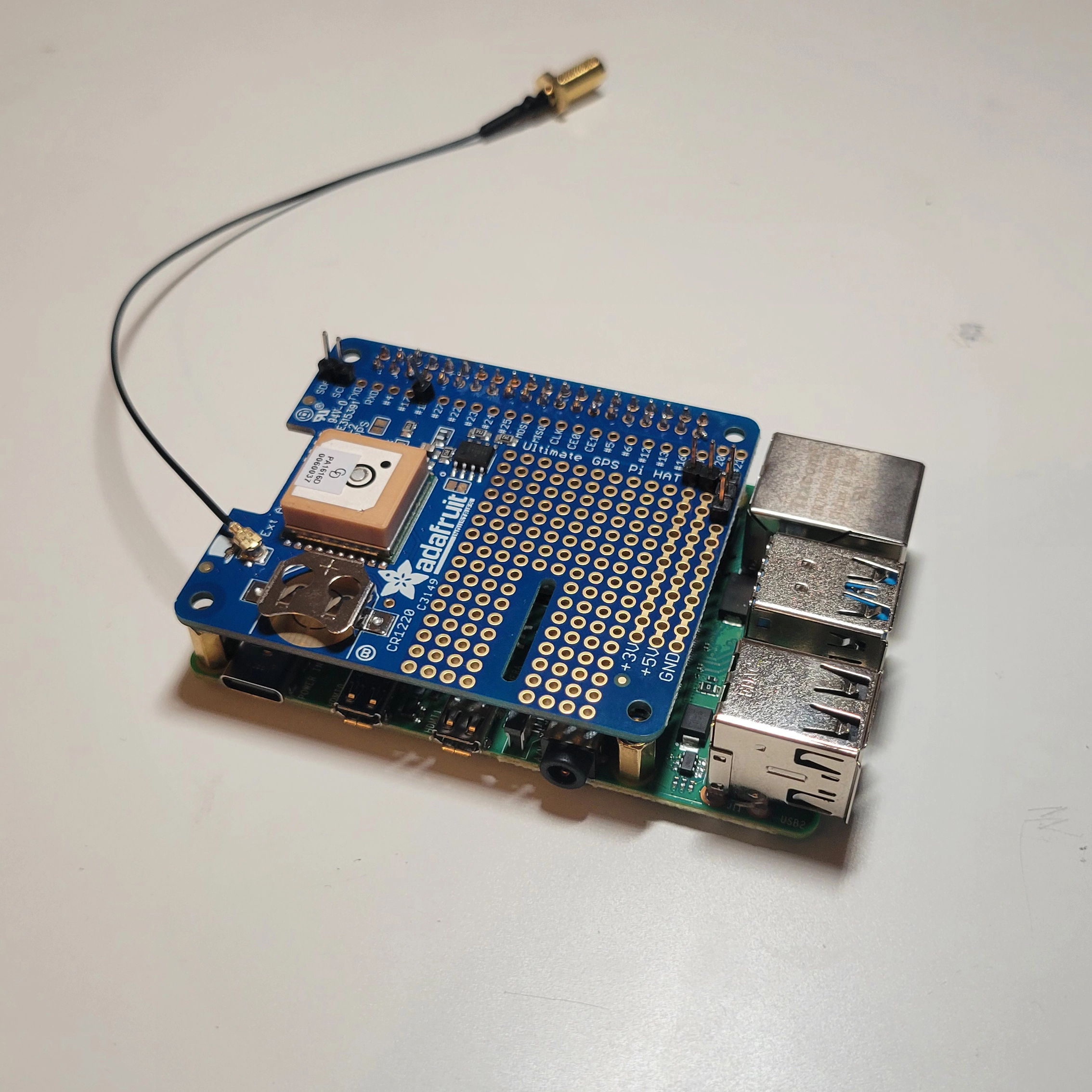
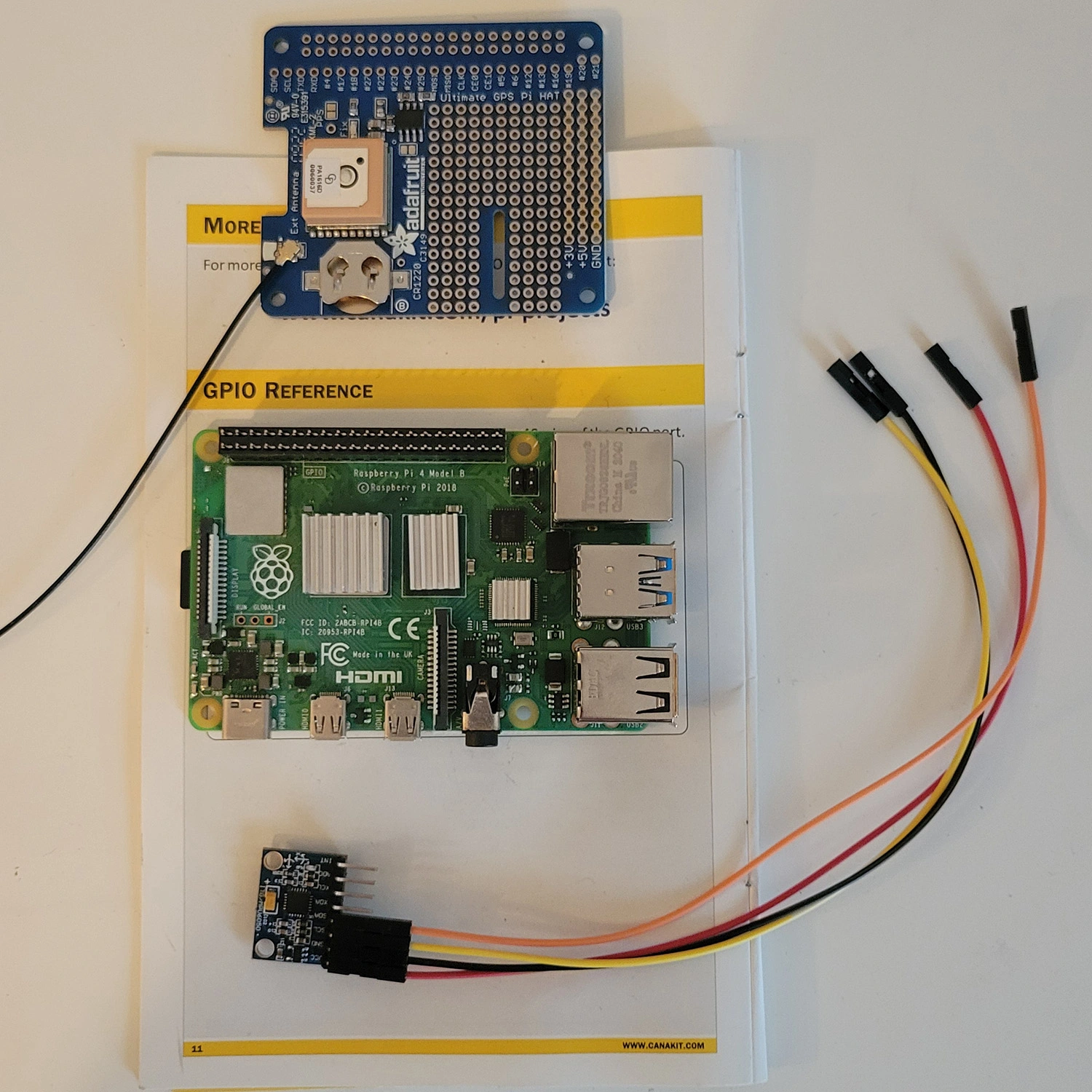
Let me explain the reasoning on why I decided to go with a Raspberry pi, specifically a pi that is running android 13 on it. I was looking to learn more about android development and when I needed some gauges for the Z this just seemed like the perfect opportunity. Why use a pi? Well because they are cheap, I had one lying around, they have bluetooth which in order to retrieve data from the ECU I had two options either tap into the CAN bus of the Z and try to decode the data or two simply use a OBDII scanner and connect to that via bluetooth. I opted for option two and am using an OBDII scanner, specifically this one. The downside to this compared to CAN bus is that in my case I get slightly less data, for example I can not access the oil temp sensor data and the data transfer speeds are also slower. But for my purposes and must other purposes this is perfectly fine and I still get access to all the important data I want. Another plus is that the GPIO pins on the Raspberry pi allowed me to set up a shut down script easily plus the added benefit is that I could expanded the features I need in the future to use hardwired data inputs like (gps, accelerometer, gyroscope, etc.) all of which are features I ended up adding. More on those additional add ons, I am running a Adafruit Ultimate GPS HAT for Raspberry pi this gives me access to GPS features so I can track things like lap times, 0-60 times, speed and other GPS related features. In the future, I plan to integrate these capabilities into the Android app I’m developing to display all this data. Now I also have another add-on board that has an accelerometer, and gyroscope on it to collect more data for things like a G-meter and another way to collect data during track days. Here is the module I am using. To get this all working together I soldered on some new pins to the adafruit HAT on the: SDA, SCD, #18 pin (for shutdown script), three GND, one 5v, one 3v and then was able to connect that to my MPU-6050 module. All you need to do to get this working is connect the SDA and SCD pins plus a 5v power and ground from the pi to the MPU-6050 module to the ones on the adafruit or GPIO pins on the Raspberry pi. This lets everything talk and work together.
Display and Outputs:
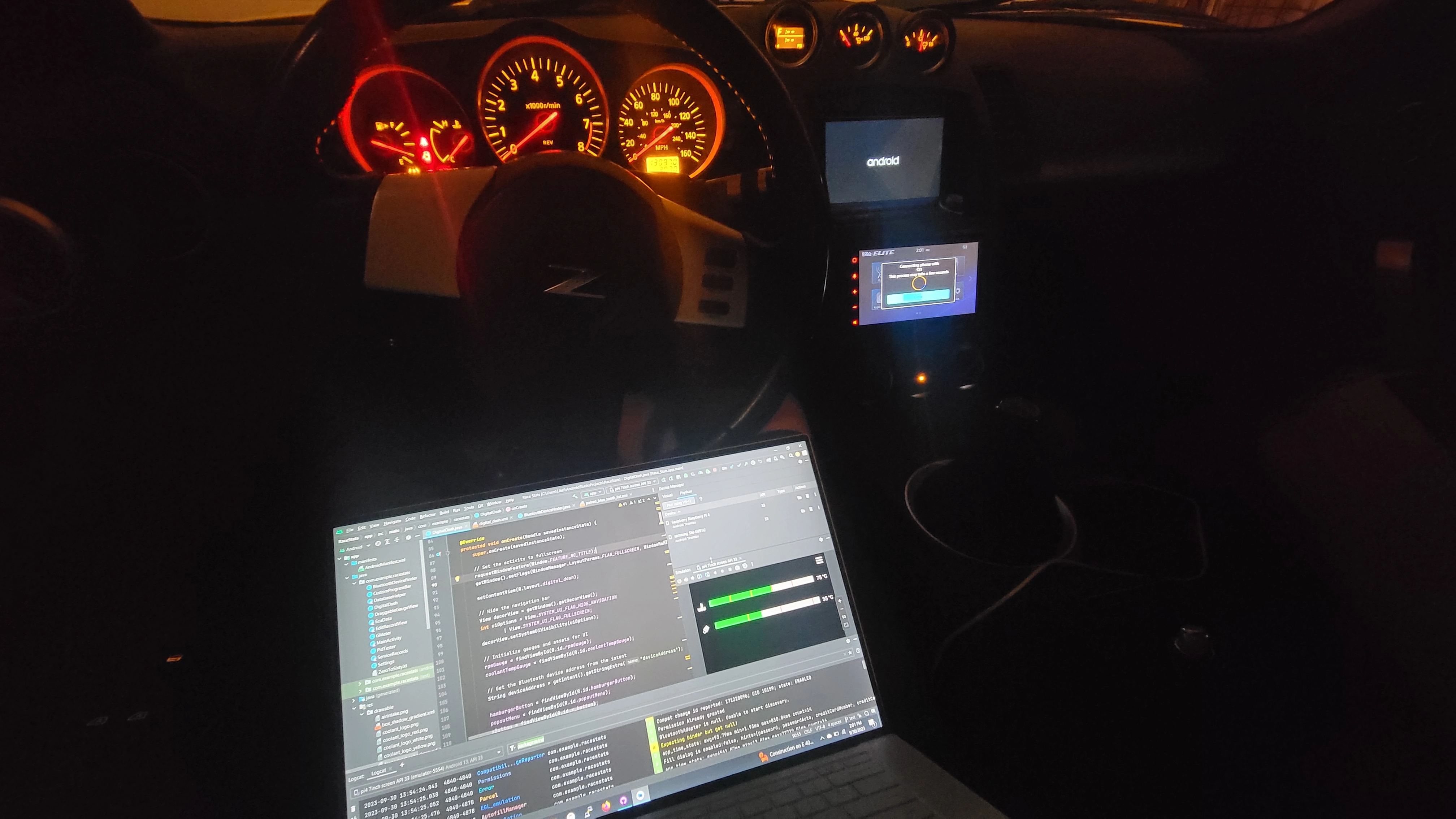
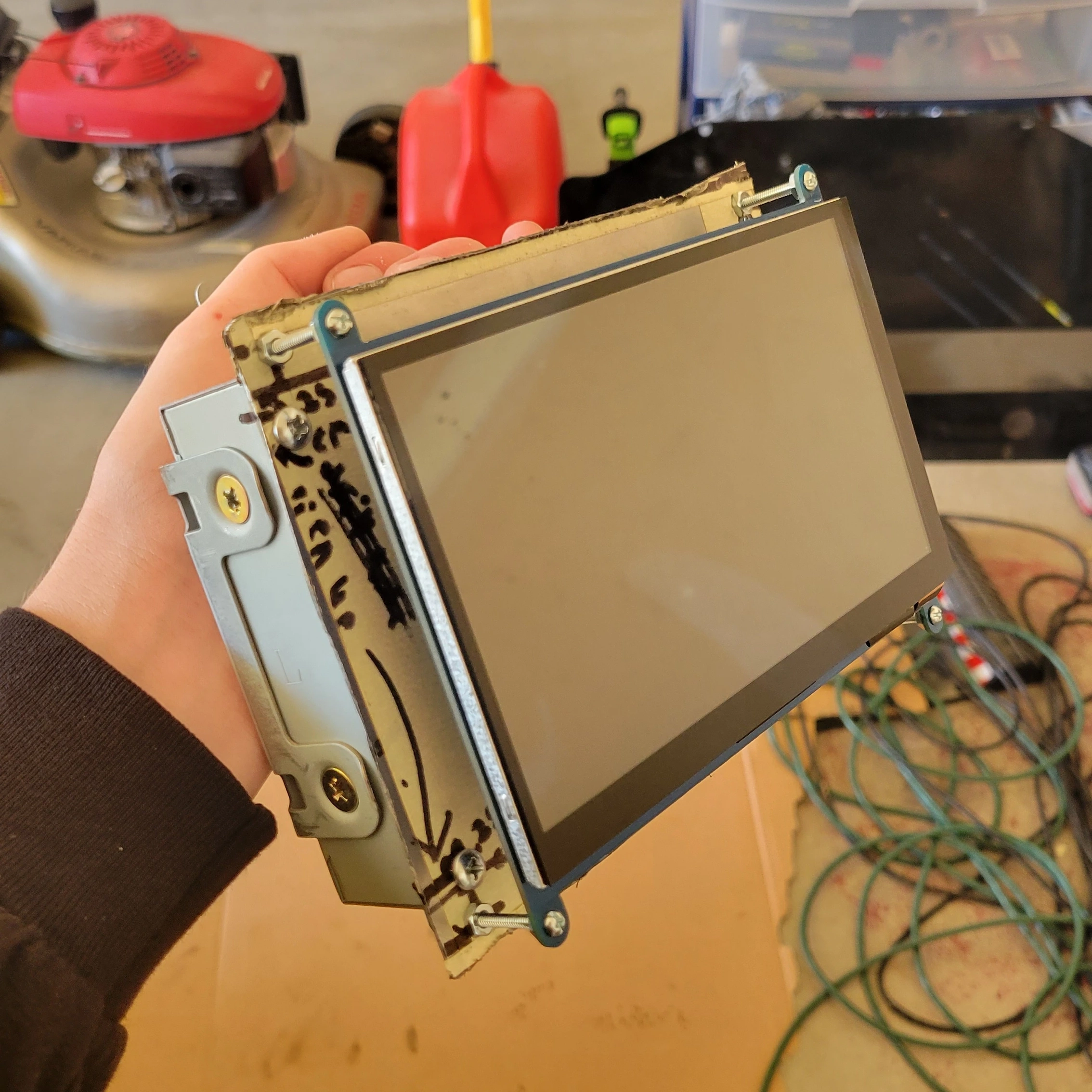
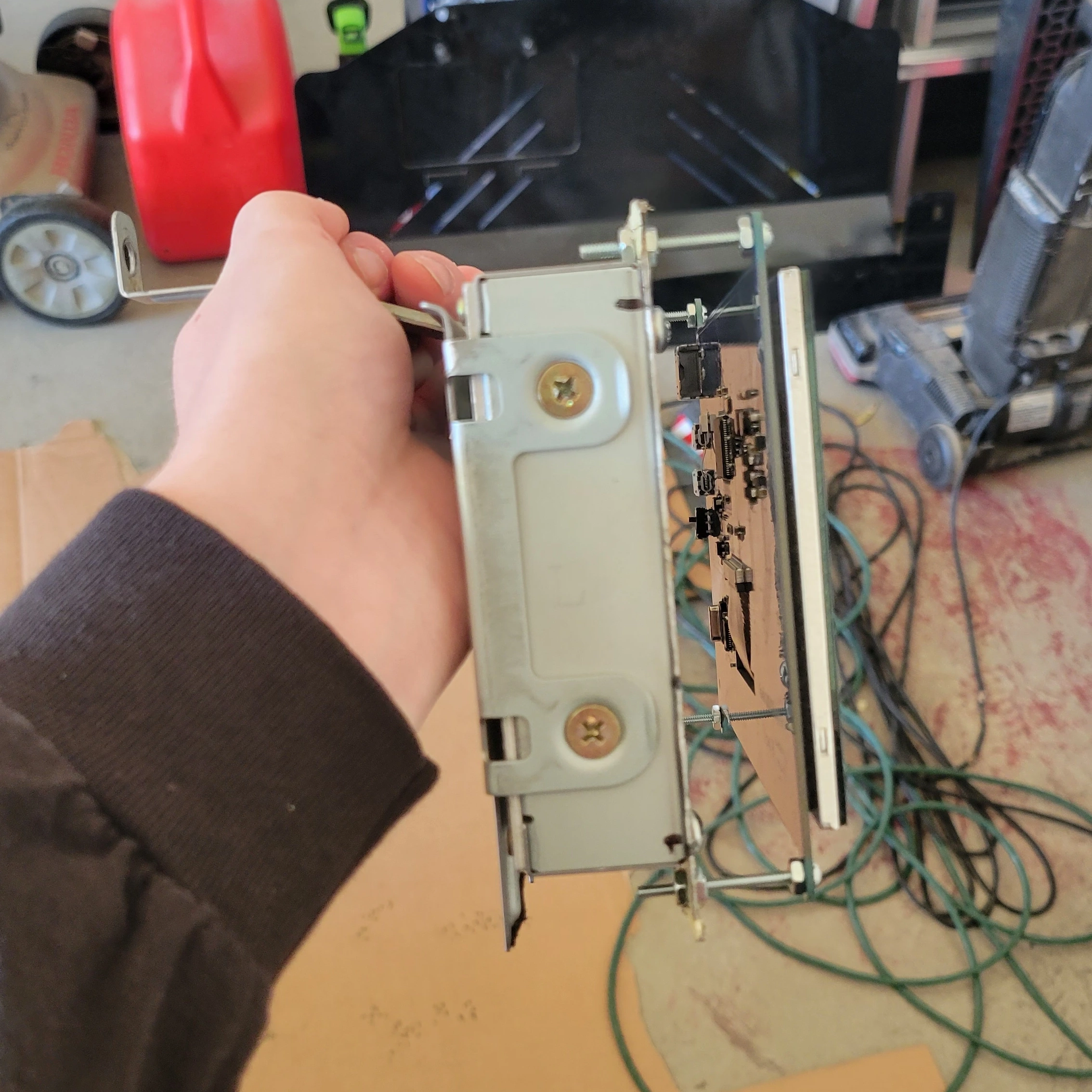
Finally, how do we actually display the data, and how can you, the user, interact with it? Well I found the perfect solution for my self. My 350Z has an opening where the factory navigation system used to be. Since it hasn’t worked since I’ve owned the car, I decided to remove it and replace it with a 7-inch touchscreen display like this one.
To install the screen, I ran an HDMI cable and a Micro USB to USB-A cable from the screen’s location back to the glove box area behind the passenger seat, where I store the Raspberry pi and all the additional hardware. Note that I had to use a 270-degree HDMI adapter to make the screen fit properly and also trim a bit of the plastic inside the dash. All the cutting is internal and not visible once installed.
In my case, the cover that normally goes over the navigation opening is missing, so trimming the inside wasn’t an issue. However, if you still have the cover in your 350z, you’ll want to make sure your modifications don’t interfere with its opening and closing mechanism.
Mounting the Screen:
In order to get the screen to sit flush with the trim I made a custom mount using parts of the old factory nav mounting system to get the angle right plus my own custom bits using some bolts and nuts to get the depth right. If I were to make this again I would 3D print something. But if I learned anything from intro to engineering it’s that adjustability can make your life much easier and in this situation it did, as it took a lot of adjusting to get the screen to sit just right.
The Software:
The software I am running on this is a custom android app called Android Race Dash or ARD for short that I am working on in my free time. Though I don’t have much of it these days, so development is pretty slow since I am not only learning how to develop android apps in the process but also need to engineer some pretty complex operations to get all the features I want to run efficiently given the OBDII protocol is not the fastest thing in the world. If you are wanting to do this yourself, I would recommend going with the torque pro app while I am still in the process of developing Android Race Dash. Here is the GitHub Repo if you want to fork my work or contribute to the project.
Powering the Raspberry pi 4B in a Automotive Environment:
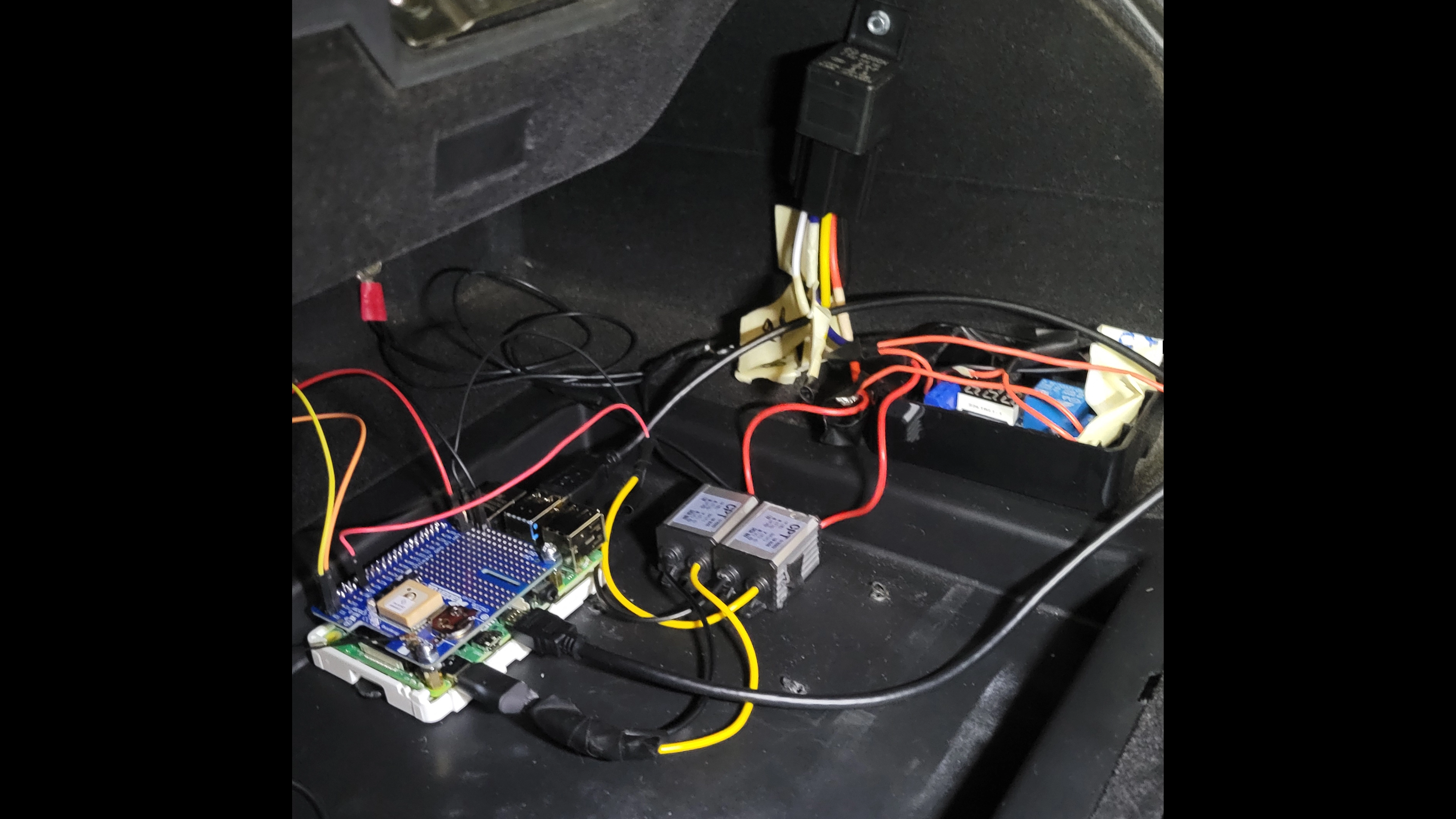
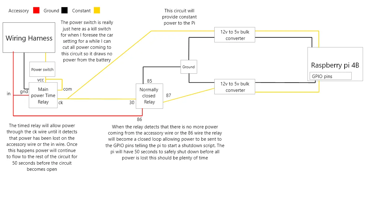
Now let’s dive into the wiring, the nitty-gritty details of connecting the Raspberry pi to the car's electrical system efficiently, while avoiding unnecessary battery drain when the car is off. Below is the complete wiring diagram I created. Following this and installing my shut down script will yield you the same results that I have in my set up.
I am no electrical engineer so there might be an easier way to do this without the relays. That being said, this setup is working great and I’ve had no issues.
The Raspberry pi 4B requires 5V to run, but since cars provide 12V, I needed to step the voltage down. To do this, I used 12V to 5V DC-DC Buck Converters, these ones specifically. While you can buy these converters with a built-in USB-C output (making them plug-and-play), I decided to make my own connector instead of waiting for another part to arrive.
Here's what I did:
- I cut the USB-C connector off an old cable, stripped the wires, and soldered the positive and negative wires to the 5V output of the buck converter. This DIY approach works just as well and retains the Raspberry pi’s factory surge protection system, which is important for automotive environments with potential voltage spikes.
I would recommend the simpler solution and just buy a buck converter that already comes with a 5V USB-C output and another with the 5v bare wire output for the GPIO pins, but the way I did it is just as good if you have the spare parts lying around and the know-how.
Wiring the System: Accessory, Ground, and Constant Power
Next, I tapped into the car’s wiring harness behind the stereo to get power. Specifically, I used:
- Accessory power wire: This wire only provides power when the key is in the ignition and turned to the "ON" position. It serves as the trigger to start the system.
- Constant power wire: This wire supplies 12V at all times, even when the car is off, to keep the Raspberry pi powered during the shutdown process.
For the ground, I connected the circuit to a ground wire in the stereo harness, which is grounded to the chassis. You can also ground it directly to any suitable point on the car’s frame.
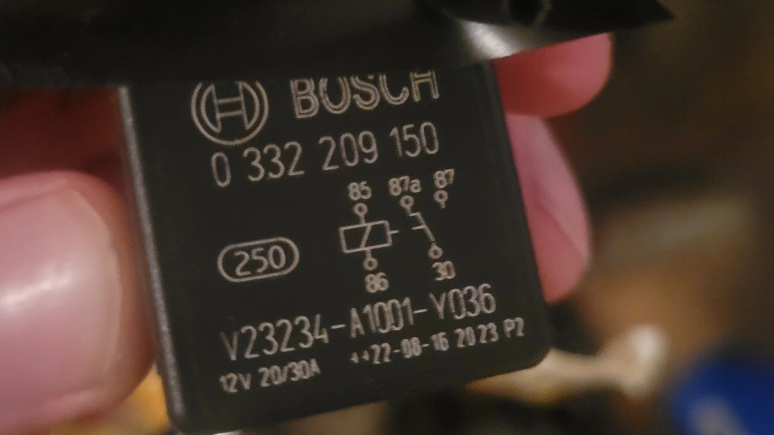
Managing Shutdown with Relays
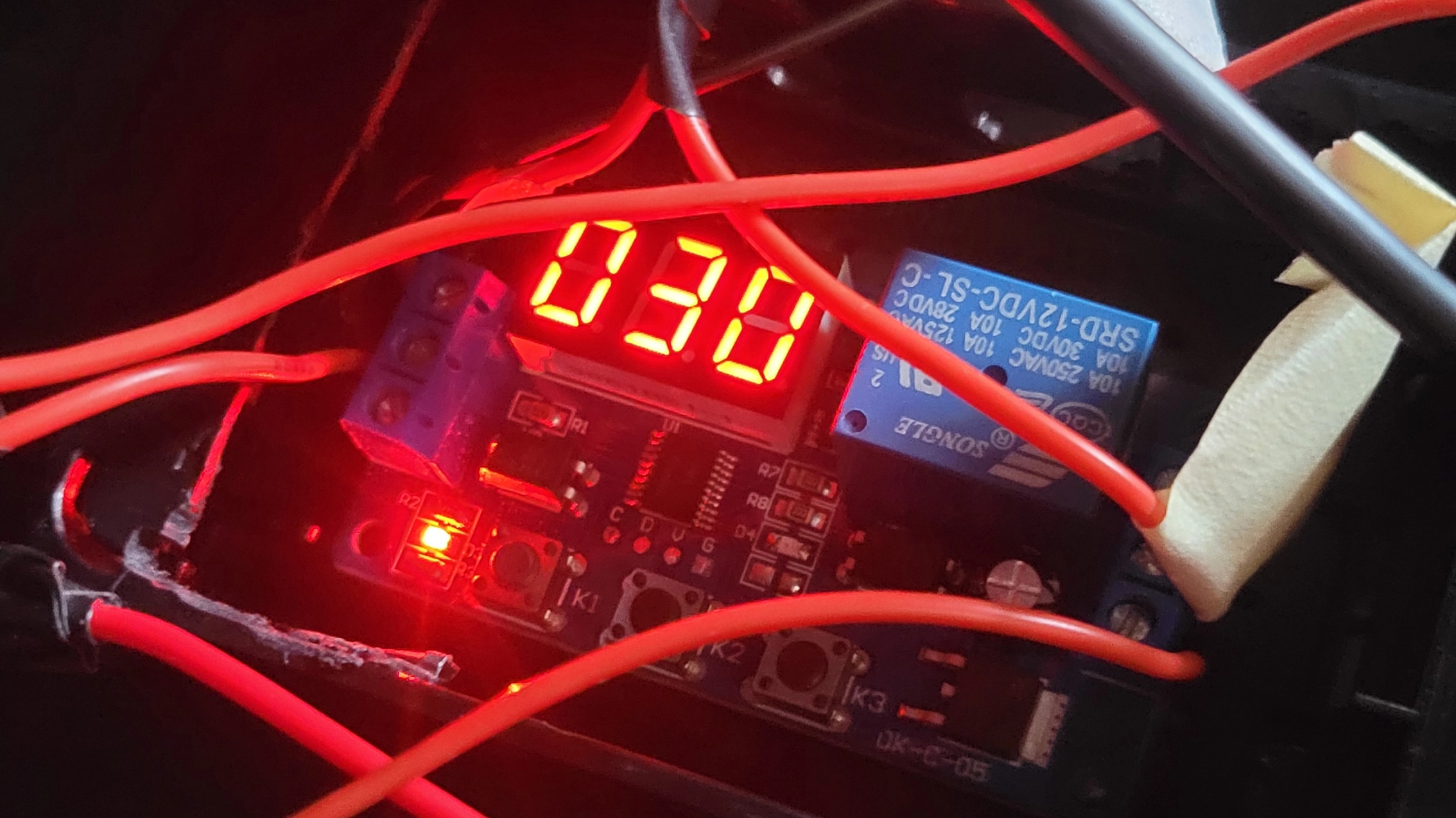
To avoid cutting power to the Pi abruptly (which could corrupt data or damage the SD card), I added a Main Power Timer Relay and a Normally Closed Relay:
-
Main Power Timer Relay:
When the accessory power wire loses power (e.g., the car turns off), this relay continues supplying power to the Raspberry pi for 50 seconds. This gives the Pi enough time to execute a safe shutdown sequence. -
Normally Closed Relay:
This relay monitors the accessory power wire. When it detects that accessory power is off, it sends a signal to one of the Pi’s GPIO pins (I used GPIO Pin 18) to initiate the shutdown script.
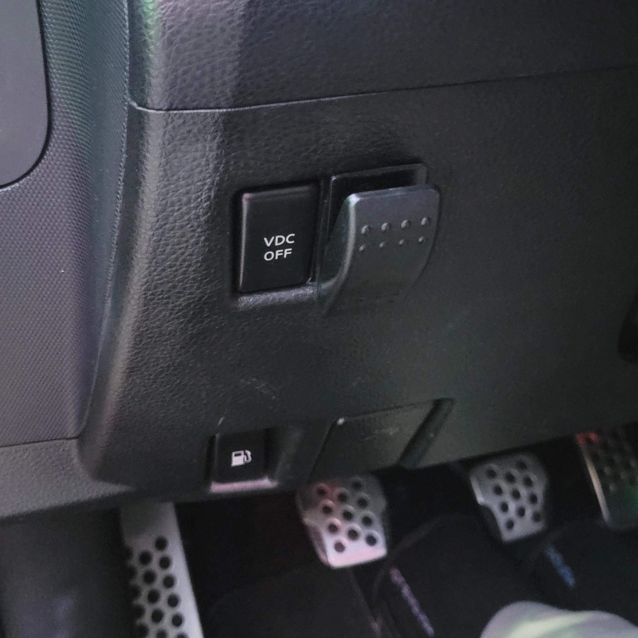
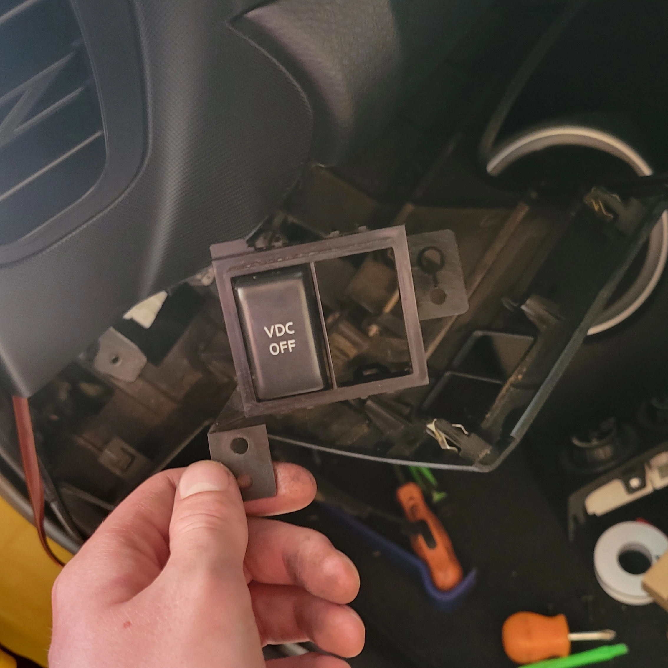
Finally, I added a kill switch to the system. This allows me to manually cut all power to the Raspberry pi and relays when the car will be parked for an extended period, preventing battery drain.
Writing the Shutdown Script for the Raspberry pi:
The shutdown script is a small piece of code I wrote in C, which monitors GPIO Pin 18 for a high signal. When the Normally Closed Relay sends power to this pin, the script tells the Raspberry pi to begin the shutdown process.
The script itself was straightforward to write, but getting it to work on an Android-based OS running on the Pi took some trial and error. Here’s what I did:
Place the script in the /system/bin directory, as this is where executable scripts are stored in Android. Set the correct permissions using the following command:
chmod 755 /system/bin/shutdown_script.shSince modifying files in the /system directory requires root access, use the su command before copying the script to the directory:
su
cp shutdown_script.sh /system/bin/
Mounting the Kill Switch:
Like the screen, I again got lucky and the kill switch mounts perfectly where the blank button used to go next to the VSC button in the 350z. The actual switch I used was this 2 pin on/off switch.
Result:
- When the car is turned on the pi automatically starts up.
- When the car is turned off, the relays signal the Pi to shut down and keep it powered for 50 seconds to let the shutdown script run.
- The kill switch prevents battery drain during extended periods of inactivity.
Link to Shutdown Script:
https://github.com/Amurdock6/Raspberry-Pi-4-Android-Shut-Down-ScriptOutro and Final Thoughts:
It’s been over a year since I installed the digital dash, and I’m happy to report that it’s been holding up
great! Overall, this project was well worth the time and money. I’d highly recommend it to anyone who needs a
digital dash and doesn’t mind tinkering or even someone who just wants to display or log data. All in all, I spent
around $280, and with this setup, I can monitor any data point the ECU supplies via OBDII, as well as additional
inputs from other sensors. Plus, the customization options and functionality far outweigh the limitations of
traditional single-use gauges.
For example, a single AEM gauge costs around $200, only displays one data point, and takes up significant space.
With this digital dash, not only do I save money, but I also get the freedom to customize the interface however I
like. The amount of functionality at this price point is unbeatable.
The main limitations are software and OBDII data transfer speeds. Torque Pro is an excellent app and meets most
needs, but it has its constraints. This is where my next project, Android Race Dash, will come in. I’m working on
creating an app tailored for this setup, but between school and work, progress is slower than I’d like. Stay tuned
for a future blog post about the state of the app and my plans for development.
OBDII speed concerns can also be addressed by utilizing the Pi’s GPIO pins to connect custom sensors for
time-sensitive data. This would allow for much faster readings, though it requires additional programming to make
use of these inputs. For less time-critical data, like temperatures, OBDII is plenty fast.
What would I do differently if I were to redo this project? Honestly, not much! One upgrade I plan to make is
switching to a faster OBDII scanner, like the OBDLink MX+, which is considered one of the fastest wireless options
for Android and is more compact than my current one.
I’d also 3D print a better mount for the screen. While my current mount has held up well, installing it was a bit
of a pain. The bolts were so close to the old nav housing that tightening them required some awkward maneuvering,
and the process involved a lot of dremeling and drilling. Although it works fine and keeps the screen flush, a
3D-printed mount would have been much easier to install and replicate in the future.
Aside from those small tweaks, I wouldn’t change much. This project went surprisingly smoothly, and I hope this
blog post saves you some of the research and trial-and-error I had to go through. It was a quick and rewarding
project overall, and I’m excited to see how it evolves over time.
Thank you for reading! I hope you found this guide helpful and that it saves you time on your own project. If you
have any questions or need advice, feel free to email me at alexanderrmurdock@gmail.com.
I’ll be happy to help however I can.
Materials/Hardware needed:
Screen - $50Raspberry pi - $83 (you can use a model with less memory and get the same result)
OBDII Scanner - $32
20 AWG Wire - $8
12v to 5v buck converters x2 - $18
Timer Relay - $10
Normally Closed Relay - $7
Relay Connectors - $11
HDMI right angle adapter - $5
HDMI cable - $7
HDMI to Micro HDMI adapter - $6
Micro USB to USB A cord - $8 (make sure you get one that supports file transfer)
Dupont Wires - $6
Optionals for more data:
Accelerometer and Gyroscope - $7Adafruit Ultimate GPS HAT for Raspberry pi - $30